Custom Framing
Example
Although the power and flexibility of the software is very strong, sometimes
a new feature or condition is needed that was never thought of or introduced
before. With just a little tweaking of existing program setups, I was able
to add the feature for Finger Jointed STUDS to BuildersCAD as a permanent,
easy function to use. I not only can control my stud use by wall but can
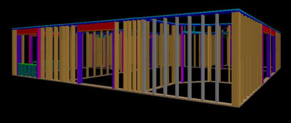
control it on a stud by stud basis. The example below shows the back
“kitchen” wall with the FJ STUDS placed only from the corner to the lead
in. They automatically frame up as GREY for easy user verification in 3D as
seen below:
Here is
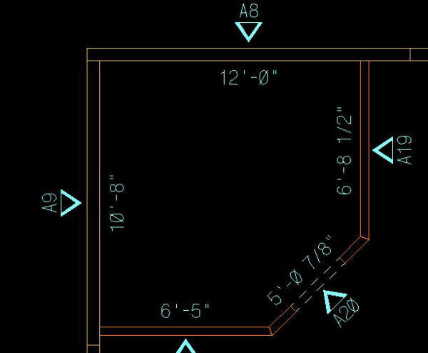
that wall section in Plan where you can see Wall A8 spans further than the
kitchen where FJ STUDS are no longer needed:
Here
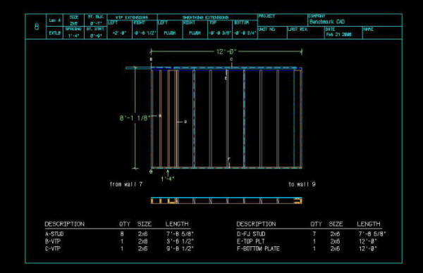
you can see the system created Elevation with cut part list including the
new FJ STUDS:
Notice
that the bottom plate view automatically calls the new FJ STUDS out with a
unique “stamp” so that they can easily be recognized in a black and white
print out.
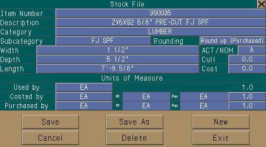
By
adding the material to my stock file and piece use table,
The
system automatically will now calculate the correct PULL LIST, CUTTING LIST
and MATERIAL LIST as seen below:
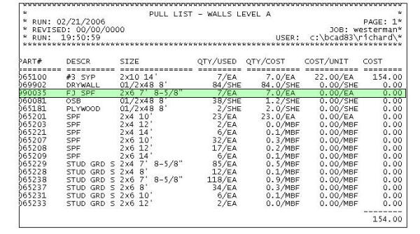
A great
thing about BuildersCAD is that it can be easily customized to fit almost
any need. After 20 years of development around customer wants and needs,
most variables are there already or the tools to make that change are there,
as demonstrated with this FJ STUD example.


