Dual channel bass/guitar blackface-style 1U preamp
with transformer balanced low impedance outputs

Dual channel blackface-style guitar/bass preamplifier |
||
| Version
2 (2010/11) |
Version
1 (2004) |
|
| Chassis
form factor |
1U rack mount, 10
inches (255 mm) deep |
1U rack mount, 6
inches (150 mm) deep |
| Internal layout |
Power supply and each
preamp channel on separate turret board |
Power supply and each
preamp channel on single turret board |
| High
voltage power supply (B+) |
>= 300VDC @ 40
mA. Enough filament and B+ current for several
preamp tubes per channel |
240 VDC @ 3 mA.
Only enough filament and B+ current for one 12AX7
per channel |
| Output |
high current,
low-impedance transformer balanced output on XLR and
1/4" TRS phone jacks, >16V rms at clipping into
600 ohm load |
capacitor-coupled
high impedance unbalanced output on 1/4" phone
jacks, ~2V rms at clipping into 10k ohm load |

Chassis form factor
As in my first dual preamp project, I wanted to retain a 1U
rack mount form factor. With the additional features
and larger power requirement of this project, though, I
needed a deeper rack box. I selected a Par-Metal
10-19112B steel and aluminum chassis, with a net
internal depth of 10" (255 mm), and an internal height of
1.42" (36 mm). The chassis is very strong, with a
0.125" (3.2 mm) anodized aluminum front panel, 0.06"
aluminum rear panel (U channel), and 0.05" painted steel top
and bottom plates, and painted steel channel sides. It
includes aluminum rack handles.Layout
I wanted to be able to experiment with preamp circuit variations without having to build a new platform. For example, I could build this project with a Fender blackface channel and an Ampeg B15 channel. Or I could have an Ampeg B15 channel and an SVT channel. Or I could assemble any combination of mix-and-match preamps I might fancy. I didn't need plug-in modularity, but I wanted to be able to swap a module in a day or so without tearing the whole rig apart, so I chose to build each preamp channel on a separate turret board. The power supply filter capacitors are located on their own turret board. The vacuum tubes are mounted horizontally to the chassis behind the turret boards on 1/16" aluminum angle bracket.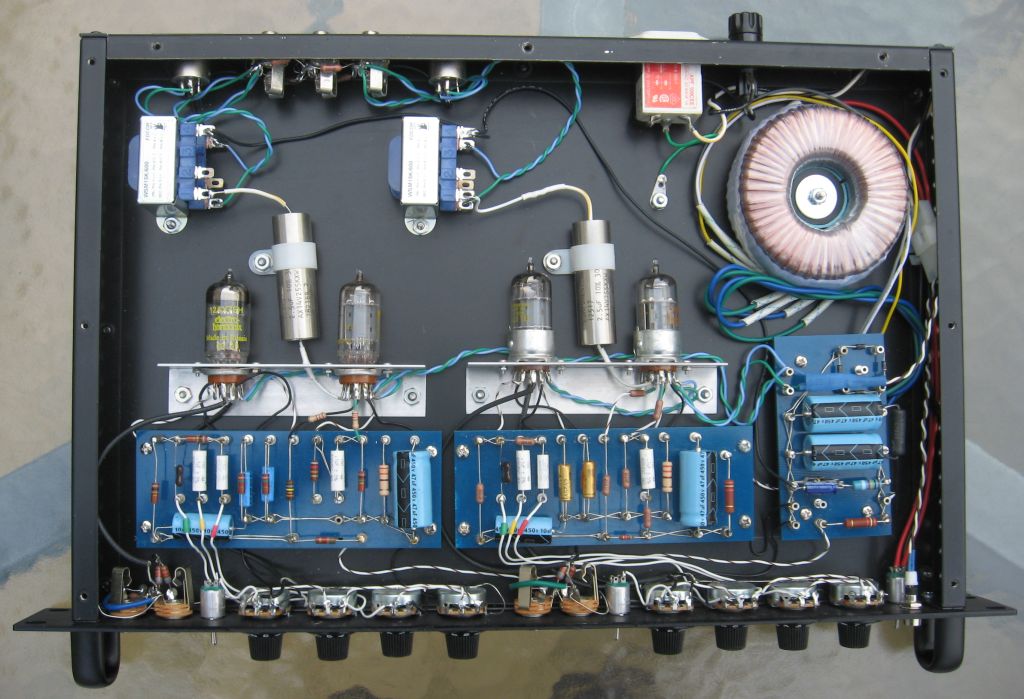

Power supply
My first dual preamp was powered by a small 6 VA power transformer with dual primary and dual secondary coils. Using one of the primary windings as a secondary and feeding it to a full wave voltage doubler gave me about 240 VDC at 3 or 4 mA. This is only enough for a single 12AX7 tube per channel. After a couple of filtering stages, the B+ was only about 170 VDC, which is kind of low for a blackface style preamp. A Princeton Reverb has a filtered preamp B+ of 240V, a Vibrolux Reverb gets 300V, and the Super Reverb, Twin Reverb, and Showman get 400+V. I wanted more clean headroom, so I needed a higher B+. Since I also wanted to be able to use two or three tubes per channel, I also needed more filament and B+ current.To obtain a filtered B+ of at least 300V, I chose an Antek AN-05T280 toroidal power transformer. It has dual primary windings, allowing operation on 120 VAC or 240 VAC mains current. high voltage taps at 260 or 280 VAC at 250 mA. It provides 2 x 6.4 VAC @ 2A filament windings, which I connected in series to obtain 12.6 VAC for the filaments. The only issue with this transformer is its height - 1.6" inches, which I think includes the mounting hardware. Without the mounting hardware, it just fits between the chassis top and bottom plates, making a perfect sandwich. To secure the toroid in the chassis, I cut a cylindrical plug from round 1.125" delrin stock (plastic), fastened the plug to the chassis with a #6 machine screw, and placed the center hole of the toroid over the plug. I measured 335 VDC at the input of the second stage filter capacitor.
Given the relatively low gain of the preamp circuit, I decided it was suitable to run the filaments on AC.
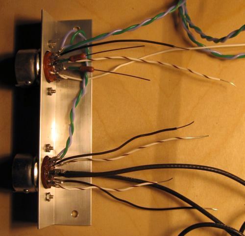
Another small chunk of learning I gained from the project concerns driving the power-on LED from the12.6 VAC filament line. It's easy to calculate the current limiting resistor to run this LED from a 12 V DC source (220 ohms), but it's not a good idea to subject an LED more than 5 or 6 volts of reverse bias. As described in this wikipedia article, I added a diode in inverse parallel to the LED to protect it from reverse voltage. The diode and current limiting resistor are encased in heatshrink tubing as shown in the below right image.
Antek
05T280 50VA toroidal power transformer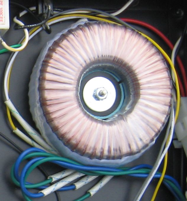 |
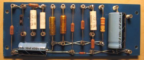
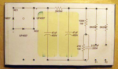
power
supply turret board with full wave bridge rectifier
diodes, 2 R-C filter stages, and filament voltage
reference divider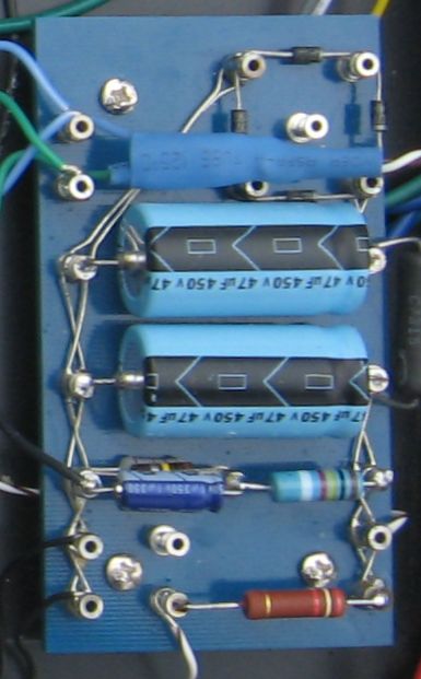 |
Preamp output
The output of my first bass preamp project coupled the plate of a 12AX7's second triode to a 1/4" phone jack with a 0.1 uF film capacitor. This high impedance unbalanced output was adequate for a reasonably sensitive power amp with a 10kohm or greater input impedance and a short cable. I wanted to be able to drive balanced line inputs of a mixing board or power amp over a long cable with minimal loss of signal fidelity and minimal noise pickup. Alembic's single channel F-1X provides a transformer balanced output, driven by some silicon. I have nothing against silicon, but in the interest of keeping my project all tube, I decided to drive the output transformer for each channel with a White Cathode Follower, optimized for maximum voltage swing. The output transformers are Edcor WSM15k/600 ohm 0.5 W plate to line units, the same model I used in my dual Pultec MB-1 microphone preamp clone. The output of each transformer connects to a male XLR and a 1/4" TRS phone jack on the rear panel. Both channels connect in parallel through 220 kohm series isolating resistors to an additional 1/4" TRS phone jack for a mono output.Both individual XLR and 1/4" TRS outputs drive about 16V peak-to-peak into a 600 ohm load. This will upset the sound engineer who expects a microphone-level input from your "direct out". These outputs were designed for driving +4 dBu balanced input power amps, like this Bryston , or your favorite Crown, QSC, etc. It would also work well into any pro signal processing equipment you might have. The mono out (1/4" TRS) is attenuated, giving 6V P-P into a 600 ohm load. In retrospect, it is desirable to be able to drive lower-level inputs without overload. Therefore, I plan to incorporate a switchable pad for each channel's output to provide 2 levels of attenuation to accommodate the input signal levels for a wider range of power amps, mixing consoles, and outboard signal processing gear.

Preamp modules
For my initial build, I went for two Fender blackface-style preamp boards, each containing a 12AX7 and a 12AU7. The first triode of the 12AX7 is a gain stage, followed by the standard passive treble-middle-bass tone stack, with the second triode providing makeup gain. Both triodes of the 12AU7 implement the output stage.White Cathode Follower
Here we depart from the standard blackface circuit. The output of the second gain stage is direct coupled to the cathode follower, which in turn is coupled to the output transformer by a 2.2 uF polycarbonate film capacitor (mil-spec things that apparently aren't made anymore). A consequence of direct coupling the second gain stage to the WCF (12AU7) is the grid of the WCF is at the DC potential of the prior stage's plate, roughly 150V. In order to not exceed the maximum heater-cathode voltage difference rating of the 12AU7, the filament must be referenced to a positive voltage so the difference between the heater and the WCF cathode (DC + signal) is less than 200V. I chose a reference voltage of 90V, created by a voltage divider on the power supply board (with a 1uF filter cap) whose center point is tied to the filament windings. All the filaments in the unit are referenced to this elevated DC voltage.The design equations for the so-called optimal white cathode follower are well-documented on the internet. I first learned about it in this article by Alex Cavalli on the Headwize site, devoted to the care and feeding of headphones. The inimitable John Broskie has analyzed it at length in his Tubecad Journal . This companion article on Cavalli's own site presents the equations in very good detail..
My initial plan was to use an SRPP output stage, but the additional gain from this topology would have been completely excess. The parallel 12AU7 cathode follower in the Pultec would no doubt have been a fine alternative, but I thought it would be interesting to try a well-developed topology that would be new for me. Thus, the optimal White Cathode Follower.
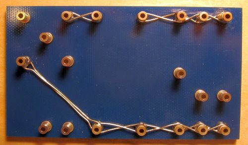
Irregularities
If you look at the pictures, the two preamp turret boards are slightly different, but the circuit is the same. I changed my output stage design from SRPP to WCF after I had drilled the first board and set the turrets. The second board was made with my slightly more compact layout for the cathode follower, allowing me to move the second filter stage resistor from the power supply board to the preamp module. I made one module with carbon composition resistors, and the other with metal film resistors. The film capacitors are Mallory 150's.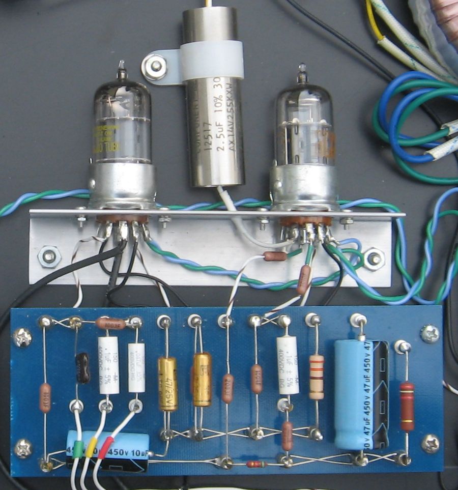
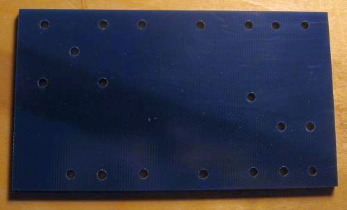
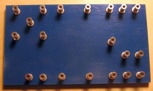
Constructing the preamp turret
board and tube sockets
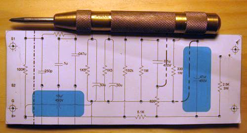
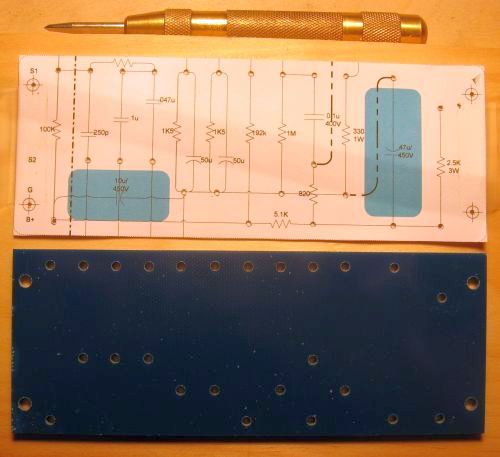
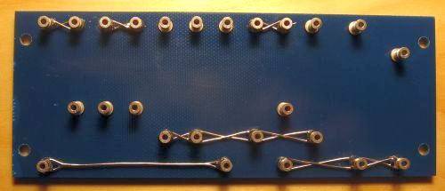
Constructing the power supply turret boardBelow is the construction sequence for the power
supply board. Note that I changed the layout
of this board in my document after I made this
prototype. I made it slightly more compact,
and changed a few of the resistor values.
|

Testing the power supply and preamp modulesI assembled a completed preamp module and the power supply module in the test fixture. An input jack and the potentiometers are assembled on another piece of scrap aluminum drilled in the same pattern as they will be on the rack box's front panel.Despite the liberal use of clip leads and quite a few unsoldered connections, everything works. Of course you've been told a thousand times, solder is not glue, and your wiring connections are supposed to be mechanically solid before you solder them. My hack for pinning down component leads and wires that are loose in unsoldered turret holes is to wedge them in with a short bit of previously clipped component lead  |
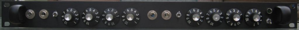
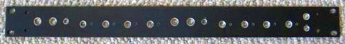
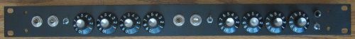
Front panel
| Front
panel, drilled and ready to mount jacks, pots,
switches, and LED. There is almost no
clearance above or below the controls when the front
panel is fit into the rack box. I had to file
away a chunk of the lip of the box's bottom panel
beneath the power toggle with a round file allow the
switch body to fit. |
 |
| Front panel with
everything mounted. These Alpha 24 mm
potentiometers are about as large as will fit
between the top and bottom panels of the rack box. |
 |
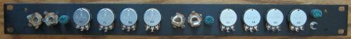
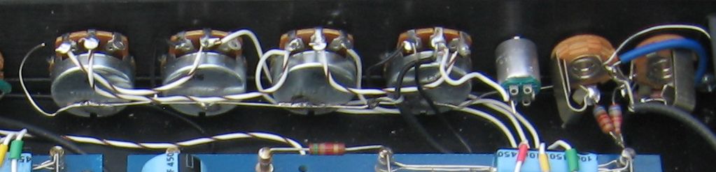
| Front panel with
everything mounted, as seen from the rear.
There is also little clearance between the solder
lugs on the pots and the top cover of the rack
box. I put a strip of cloth electrical tape
along the front of the top cover above the pots. |
 |
Assembly and testing
I placed the turret boards, transformers, power entry, fuse
holder, etc. in the rack enclosure and shifted things around
by hand until I was satisfied with the clearances and
spacings. Then I measured where things were, and
adjusted the positions to lie on 1/8" increments.
Everything went together mechanically without
surprises. Working in my usual slow way, I made the
circuit connections among the modules and the front and rear
panels. Finally I wired in the power supply
components, and made sure the B+ lines all showed high
resistance to ground. Correspondingly, I made sure all
the points that were supposed to be at ground potential had
low resistance to ground. Since I had tested the power
supply and one preamp module in my test fixture, I felt
confident that I was ready to power up. I connected
both channel outputs to my mixer's balanced line inputs with
the gains turned all the way down, bridged both channel
inputs together with a jumper cable, and plugged in my
guitar. I powered up slowly on my variable
autotransformer (a.k.a variac), and watched the power supply
voltages. Still no surprises. When I brought up
the channel volumes, one channel was perfect, but the other
channel showed about 10x as much gain, and the tone controls
did nothing. A quick check of the tone control wiring
for that channel turned up a missing ground from one leg of
the mid pot. After correcting that, both channels
worked and sounded excellent, with no extraneous hums,
buzzes, or other noises. Feeding the preamp with my HP
200CD oscillator at 1 KHz, I measured the output clipping
point at >16 V peak-to-peak into the mixer input.
The frequency response extends down to 17 Hz and beyond 20
KHz with the tone controls set as flat as can be achieved
with a Fender TMB tone stack. Clipping point for the
inputs is about 1.4 V peak-to-peak. Some players with
a high-output instrument or a percussive style prefer to
substitute a lower gain tube for the 12AX7, such as a 5751,
12AY7, or even a 12AU7.Next
- I still need to electrochemically etch the front and
rear panels. I will be experimenting with
processes for this before I try it on this
project. Since it won't work on anodized aluminum,
I will probably make a new front panel blank from
non-anodized aluminum. Fortunately, it is
otherwise uncomplicated to fabricate.
- I simulated the power supply and preamp circuits in LTSpice IV. I may post the schematic files created for this.
- Update the Visio documentation to show the wiring from the AC mains to the power transformer and the power supply board
- Upload Excel spreadsheet with bill of materials
- Try some experiments with output pads to add signal
level flexibility.
- Begin studying other bass preamp circuits for ideas to
try in a new preamp module.
Send me an email if you have questions or comments about
this project.