Bass guitar preamplifier in the Ampeg SVT tradition

These pages describe the design and construction of a 1U rack mount bass preamplifier. The design was adapted from the preamplifier section of the classic Ampeg SVT.

- The SVP-CL was a superset of the SVT preamp main channel, following the classic original's gain structure and tone shaping functions exactly.
- It used the common 12AX7 and 12AU7 tubes, instead of the SVT's 12DW7's
- It fit the entire preamp into a 1U rack chassis
- It used normal toggle and rotary switches for various
tone shaping controls, instead of the custom rocker
switches found on the SVT.
- It used a regulated DC filament supply
- It incorporated a number of useful modern features not found in the original SVT
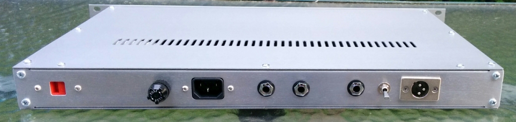
- transformer balanced line output, switchable between pre- and post-eq
- input pad
- tuner output
- two additional ultra-low tone settings and two more
semi-parametric midrange frequency choices
- A legible factory schematic was available.
My version of the rack mount SVT preamp differs from
Ampeg's in the following ways:
- My circuit is built boutique-style on 0.125" G10-FR4 (Garolite) using turret terminals; the Ampeg is built on a machine-made PCB.
- I increased the high voltage power supply B+ by 20 volts, and inserted two more decoupling/filtering stages than the Ampeg.
- Filaments are referenced to 77 VDC from a 1/4 voltage
divider on the B+ supply to reduce heater to cathode
voltage on the direct coupled stages
- I added a 120V / 230V voltage selector as the client
for whom I built this lives in Europe.
- I omitted two features of the SVP-CL: footswitch
muting and LED clip indicator. I left them out
because these required transistors that I didn't have
space for in my layout, and I did not think they
contribute anything sonically to the circuit.
Design and construction issues
There were several design and construction challenges:- The turret board layout had to be developed from
scratch, as the original SVT and SVP-CL circuits are
built on PCB's. I describe how I did it here
- The heart of the semi-parametric midrange control is a
custom part, a multi-tapped toroidal inductor. The
inductances are specified on the schematic, but:
- The inductor is not readily available as an Ampeg
service part, though they occasionally show up on
ebay. You might be able to order one through a
DIY friendly Ampeg authorized service technician.
- One boutique transformer manufacturer (Mercury
Magnetics) offers their version of this part for
>$100 each
- I hand-wound the inductor myself, using a winding recipe that I calculated by non-destructively reverse engineering an Ampeg service part that I purchased on ebay. I describe the process here.
- Ampeg designed the high voltage B+ power supply and the regulated filament power supply around a custom power transformer. I adapted this design to use a readily available catalog toroidal power transformer. The details of the design and construction of the power supplies are here.
Details, details
Wiring for the switches, jacks, potentiometers, and tube
sockets is documented here..
Schematic / Layout of the circuit except for the power
supply is documented here.
Schematic / Layout of the power supply is here.
Mechanical layout is here.
This project required a well-finished front panel. I
describe how I did that here.
LTSpice simulation of the circuit, and the schematic
resulting from that process is here.
The bill of materials is documented here..
Results
If you decide to build the project from my documentation
I believe that this preamplifier can be
constructed by intermediate to advanced builders.
However, it is quite a tight fit for the 1U box I
used. The mechanical locations and dimensions shown
in the full-size layout drawings have not been carefully
checked against the as-built unit. Builders should
physically check the mechanical fit and clearance for all
components before drilling and machining. I have
checked the circuit schematic / layout drawings pretty
well. However, it is still possible that a few
wiring connections may be missing, or incorrect on the
documentation. I (or preferably several other
builders) will have to actually build the project using
the documentation to verify that it is correct. It
is likely that you will want to or need to use some
different components in your build due to availability or
preference. You will have to determine if the
substitute will work electrically or mechanically, though
I may be able to help you with this.
I have provided email help to builders from
all over the world who have built my prior projects.
I hope my documentation will prove useful, and I will
attempt to correct any errors you find, or to add missing
information you suggest. You should have already
successfully built several vacuum tube projects before
attempting this one, and to understand and to follow safe
design and work practices for building and repairing mains
operated electrical equipment.
Other builders have completed this project!
Final notes
My construction survived its trip across the
Atlantic Ocean, and is now happily employed by the client,
who reports that it sounds wonderful, better than an SVT.
During my research for this project, I did
not find any well-documented DIY builds of a
feature-complete SVT or its preamp. There was this
thread on GroupDIY, where Okabass built what looks
to be a complete SVT-like preamp and amp. I found
another thread on a forum I can't seem to find at the
moment that showed a few pictures of an SVT preamp that
someone built in the 70's or 80's, also with no
documentation.
So I present this project's documentation to
those wanting to make your own version of this 1970's
icon. This is not an inexpensive project to make,
and will take considerable effort to construct. If
you are not DIY building for the challenge and
satisfaction of improving on the original, then it will be
cheaper and easier to buy a used Ampeg SVP-CL.
I might attempt to design an updated version
of the 300 watt RMS SVT power amp. Kevin O'Connor
presents a design for a SVT-like preamp and amplifier in The
Ultimate Tone Volume 3: Generations of Tone,
which I purchased while doing the research for this
project. The preamp was a very simplified design,
but the power amp seemed well thought-out for the
time. I believe a modern 300W RMS tube power amp
would benefit from a switch mode power supply (SMPS) with
a microcontroller to monitor and control safe
operation. The dumb linear supply has 20 kg's of
iron and copper.transformer, and things melt and/or
explode when something goes wrong with a tube or other
component. However, designing a smart 1 kilowatt
SMPS is not something I am ready to jump into right
away. If you have some technical expertise to
contribute in this area, feel free to contact me.